
Pioreactor development blog #9

💡 Optics again! This time we are discussing LEDs performance in different environments, and a major optics change to the Pioreactor.
A few months ago, we introduced temperature control via internal heating to the Pioreactor. This has been a success, and something that differentiates us from other bioreactors, but it was creating artifacts in our optical density measurements. Why is that? Well, an LED's brightness varies as the temperature changes: a higher temperature reduces brightness, and lower temperatures increase brightness. (In fact, just turning on the LED produces a significant amount of heat quickly, and so it's not uncommon to see an immediate drop in brightness - but the Pioreactor avoids this with some clever optimizations). So when the internal heating is turned on, and the vial temperature starts to rise, this reduces the infrared LED's brightness. And since our photodiodes are measuring the amount of IR scattering, we see a decrease in the optical density signal - but it's an artifact!
It actually works in reverse: if the room temperature drops, like when an outside door is opened briefly, the LED's brightness will spike (that's how sensitive our optical system is).
Another artifact is that we cycle our heating with a low frequency, about 10 minutes. This heating, and brief cooling, creates small "waves" in temperature, and hence "waves" in the IR LED brightness.
This all can be seen in the following figure, where we have set a target temperature of 35 ℃. As the temperature rises, we see a decrease in the optical density. And as the heating turns on and off in ~10m cycles, we see "waves" in the optical density as well.

Another problem that we have punted up until now is the problem of LED dimming. LEDs do have a very long lifespan, but will dim over time. It's not uncommon for an experiment to last for days or weeks, and we do not want to see a dimming artifact in our optical density.
And another problem is the the LED's output is directly proportional to the 3.3V rail on the Raspberry Pi. While the 3.3V rail is exceptionally stable, it can fall slightly when power becomes limited due to heavy CPU or peripheral use.
Wow, that's a lot of possible artifacts in optical density signal! Up until now, we've tried to use software and checks to avoid these situations, but we've come up short. Instead, we've changed our optics system to account for the IR LED brightness.
Solution
We have added a small "tunnel" that diverts some IR light directly into a neighbouring photodiode. This photodiode only measures the IR light - it isn't exposed to the scattering. This provides us with a high-resolution signal of how much IR LED is being outputted, a "reference" signal. We use this signal to correct the optical density signal (provided by the other photodiode). See Figure 2 below:

This solution is not novel, and many other optical system do this (all high quality ones do, at least). We hoped we could avoid it, as it takes up photodiode spot that could be used for other purposes. However, the results are good enough that we are happy implementing it.
Adding this has implications though. We had designed the Pioreactor such that each LED pocket was identical. This change obviously breaks that. But, I think this opens up a new, useful, design space.
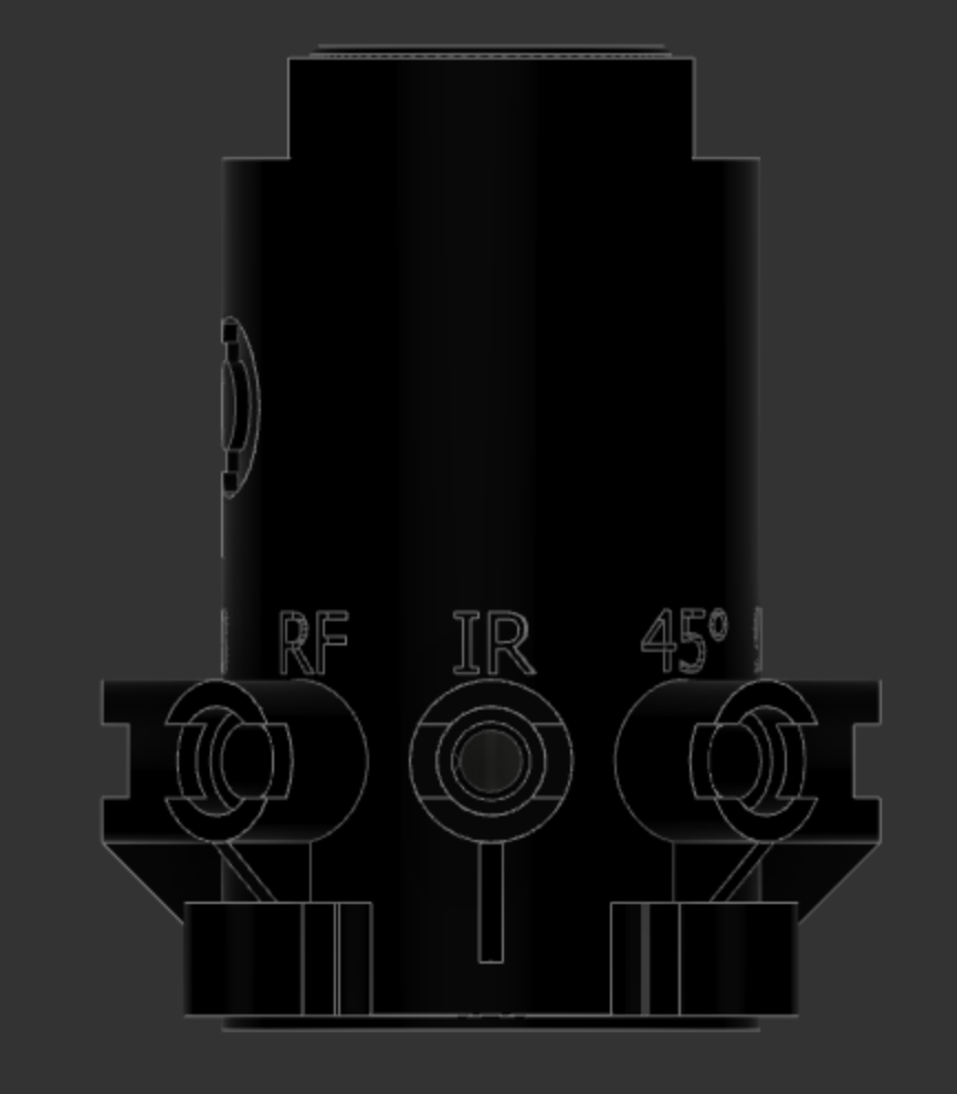
- We can now purposefully label the pockets, which will make onboarding more clear to users. We are de-bossing the labels into the 3D print. See figure 3.
- We can modify LED pockets to improve the performance of their function. For example, we've added apertures to the photodiode pockets to reduce stray light.
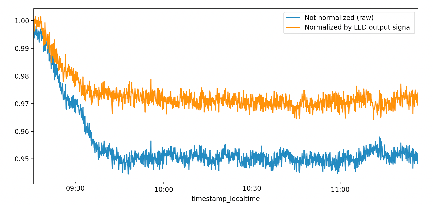
But does this new system perform well? For a demonstration, we took the optical density signal above, and normalized it by the IR LED reference signal recorded at the same tme. Figure 4 shows the result:
Conclusion
Overall, the change is a big success for Pioreactor. Of course, you don't need to use this system. The Pioreactor is designed to be flexible, so if have a better temperature system (maybe you are using a very stable incubator), you can by pass this system and use the other photodiode for something more interesting!